
Introduction
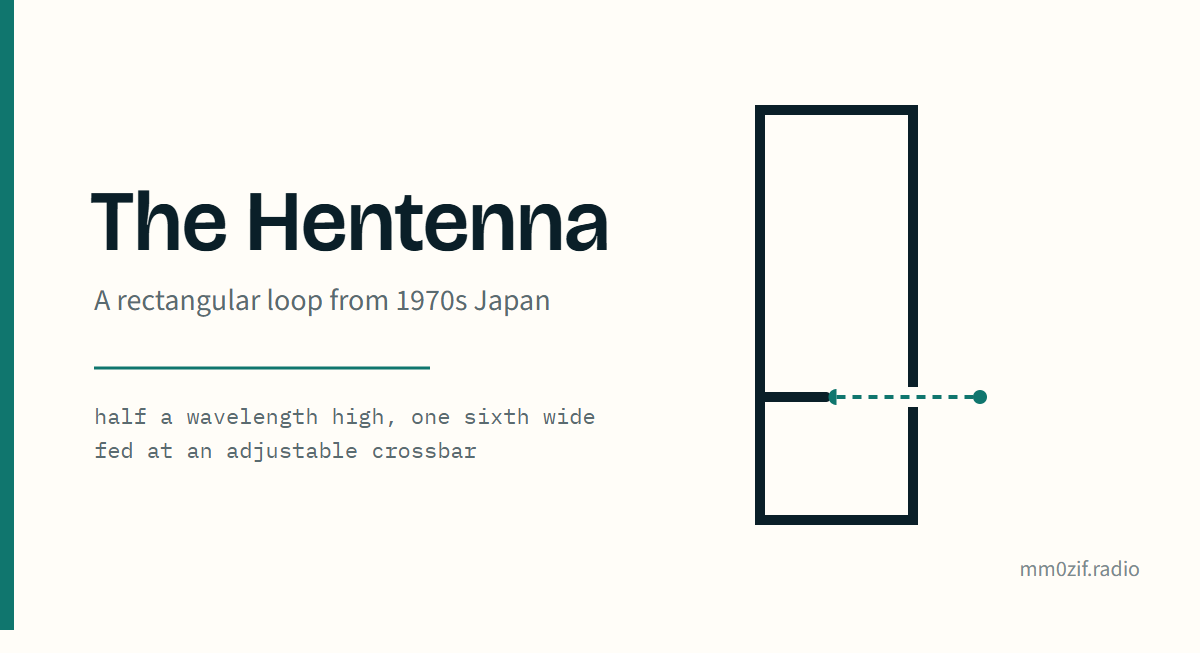
The Hentenna is an unusual and intriguing antenna design that has attracted the attention of amateur radio operators around the world for more than fifty years.
Originally developed in Japan during the early 1970s, the Hentenna is a distinctive rectangular loop antenna with an unusual feeding arrangement. Its relatively simple construction, notable radiation characteristics and ability to be scaled for different frequencies make it an attractive alternative to conventional antenna designs. Although the early experimental work was undertaken on 430 MHz, the design subsequently became particularly well known for operation on the six-metre (50 MHz) band.
It has since been adapted for a variety of amateur radio frequencies, including four metres (70 MHz), two metres (144 MHz) and 70 centimetres (430 MHz). The Hentenna is especially appealing because it can provide useful directional performance without requiring the complicated construction of a conventional multi-element Yagi antenna. It can be built using copper wire, aluminium tubing or copper pipe, depending on the operating frequency and the mechanical strength required.
In this article, we will explore the history of the Hentenna, how it works, how to calculate its dimensions and how to construct and tune one for amateur radio operation. An interactive dimensions calculator is also included, allowing you to enter your chosen frequency and calculate the basic antenna dimensions.
1. The history of the Hentenna
The Hentenna has a fascinating history that began with the enthusiasm and experimentation of Japanese amateur radio operators during the early 1970s.
Rather than being the invention of one individual working alone, the antenna developed through collaboration between several members of the Sagami Amateur Radio Club.
The original idea. The origins of the Hentenna can be traced to July 1972. Tadashi Someya, callsign JE1DEU, was a young amateur radio operator and member of the Sagami Club. He proposed an unusual antenna arrangement based on combining two loop elements. His initial idea was to investigate whether a configuration using a phase-feeding arrangement, similar in principle to the HB9CV antenna, could produce a useful directional pattern.
The original proposal was not quite the Hentenna that we recognise today, but it provided the starting point for a series of experiments. Other club members became interested in the idea and decided to investigate its possibilities.
The first experiments
The initial experiments were carried out using the 430 MHz amateur radio band.
This was a convenient frequency for experimental work because the antennas were relatively small and could be constructed and tested without requiring large supporting structures. The club had access to suitable test equipment, including a 430 MHz transmitter, a Bird through-line power meter and attenuators supplied by JR1SOP. A garden belonging to JH1ECW became one of the experimental locations.
On 10 September 1972, the first major experiments were undertaken. The original two-element arrangement proved difficult to match, so the group investigated a simpler single-element double-loop configuration. The results were surprising. The experimental antenna demonstrated a strong directional response, with deep radiation nulls towards its sides and encouraging forward gain. The early measurements reportedly indicated approximately 9 dB gain over a dipole in the forward direction. This was a result from the original experimental arrangement and should not be regarded as a guaranteed gain figure for every Hentenna.
The importance of the adjustable feed point
One of the most important developments came when Tadashi Okubo, JH1FCZ, began experimenting with the position of the feed connections.
He discovered that moving the feed point along the central section of the antenna could significantly change its impedance and improve the SWR. This was a major breakthrough. Rather than relying on an elaborate matching arrangement, the antenna could be adjusted by changing the position of the feed connections. Further experiments investigated the effects of changing the width of the rectangular loop. On 12 November 1972, the club tested several antennas with a common height of half a wavelength but different widths. The configurations included approximately:
- 0.25 wavelength
- 0.22 wavelength
- 0.15 wavelength
- 0.08 wavelength
The results demonstrated that changing the width affected the optimum feed position and matching characteristics. The version with a width of approximately 0.15 wavelength produced the lowest measured SWR in that particular series of experiments, reaching approximately 1.2:1. These experiments helped establish the proportions and adjustable feeding arrangement associated with the Hentenna.
Who invented the Hentenna?
Several Japanese amateur radio operators contributed to the development. The main contributors were:
- Tadashi Someya – JE1DEU: proposed the original antenna concept.
- Tadashi Okubo – JH1FCZ: played a leading role in the experimental development and promotion of the design.
- JR1SOP: supplied high-frequency test equipment.
- JH1ECW: provided the location for the early experiments.
- JA1RKK: credited with giving the antenna its distinctive name.
Other members of the Sagami Club also contributed to construction, measurements and testing. The Hentenna is therefore best regarded as a collaborative development of the Japanese amateur radio community.
Where did the name Hentenna come from?
The name Hentenna comes from the Japanese word hen (変), meaning strange, unusual or curious.
This was an appropriate name because the antenna looked rather different from conventional antennas and demonstrated some unexpected electrical characteristics. The name is a combination of the Japanese word hen and the English word antenna. It has remained in use internationally ever since.
The Hentenna reaches the international amateur radio community
Following its development in Japan, information about the antenna began appearing in Japanese amateur radio publications.
A key contribution to its international popularity came from Tadashi Okubo and his newsletter, The Fancy Crazy Zippy. In February 1982, Koji Sugihara, JJ1UMS, introduced the Hentenna to American readers through an article in QST magazine.
The design subsequently appeared in other amateur radio publications, including the ARRL Antenna Compendium series. By the late 1980s, the Hentenna was becoming increasingly familiar to English-speaking radio amateurs. The antenna had developed from an experimental project undertaken by a small Japanese radio club into an internationally recognised antenna design.
The Hentenna today
More than fifty years after its original development, the Hentenna remains an interesting antenna construction project.
Modern antenna modelling software, including NEC-based applications, allows radio amateurs to investigate the effects of changing conductor diameter, loop dimensions and feed position. Modern test equipment, not least the NanoVNA, also makes it much easier to measure the antenna and experiment with different configurations. The Hentenna remains an excellent example of what can be achieved through amateur radio experimentation, collaboration and a willingness to try something different.
2. What exactly is a Hentenna?
The Hentenna is generally described as a rectangular loop antenna with a distinctive internal feeding arrangement.
Its basic structure consists of a tall rectangular conductor with an overall height of approximately half a wavelength and a width of approximately one-sixth of a wavelength. The feed connections are positioned on the two vertical sides of the structure and connected across an internal horizontal section. This arrangement is central to the antenna’s electrical design.
The Hentenna should not simply be regarded as a conventional rectangular loop with a coaxial cable connected at an arbitrary point. The dimensions, feed position and conductor arrangement all influence its performance. The antenna is generally bidirectional, with its main radiation directed broadside to the plane of the loop.
3. How does the Hentenna work?
The Hentenna operates through the current distribution around its rectangular conductor arrangement.
The electrical characteristics are influenced by several factors:
- Overall antenna height.
- Width of the rectangular structure.
- Diameter of the conductor.
- Position of the feed connections.
- Installation height above ground.
- Nearby conductive objects.
The unusual feeding arrangement produces a radiation pattern that differs from that of a conventional dipole. The antenna has two main directions of radiation, with reduced radiation towards the edges of the rectangular structure. Its directional characteristics make it well suited to amateur radio operation.
However, the actual gain and radiation pattern depend on the exact design and installation. Published gain figures should be treated with care because different constructions and measurement methods can produce different results.
4. Understanding the Hentenna dimensions
One of the advantages of the Hentenna is that its basic dimensions can be calculated mathematically using the operating wavelength.
A good starting configuration is:
| Dimension | Basic proportion |
|---|---|
| Overall height | 1/2 wavelength |
| Overall width | 1/6 wavelength |
| Feed position | Adjustable |
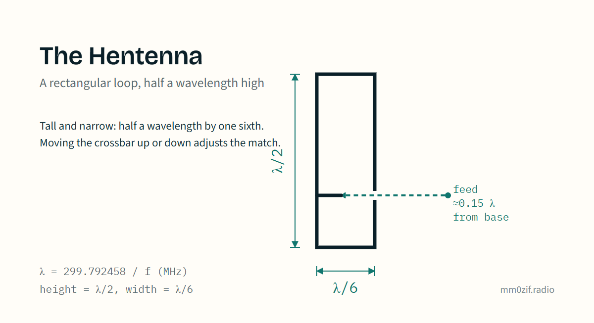
The feed position is deliberately adjustable because the original Japanese experiments demonstrated that its position has a marked effect on impedance matching.
Some published designs use a width closer to 0.15 wavelength, rather than exactly one-sixth wavelength. The final dimensions should therefore be treated as a starting design for experimentation.
Calculating the wavelength
The wavelength is calculated using:
Wavelength (metres) = 299.792458 ÷ Frequency (MHz)
For example, at 70 MHz: 299.792458 ÷ 70 = 4.2827 metres. The basic dimensions are therefore:
- Height: 4.2827 ÷ 2 = 2.1414 metres.
- Width: 4.2827 ÷ 6 = 0.7138 metres.
This gives a starting antenna approximately 2141 mm high and 714 mm wide. The dimensions are free-space calculations and may require adjustment once the antenna is constructed.
Using the Hentenna dimensions calculator
The calculator included with this article allows you to enter your chosen operating frequency and automatically calculate the basic antenna dimensions.
It also allows you to select the units of measurement and an adjustable feed-position reference. This is helpful when designing antennas for the four-metre, six-metre, two-metre and 70-centimetre amateur radio bands.
5. Choosing the construction materials
Three materials are commonly used: copper wire, aluminium tubing and copper pipe.
Copper wire
Copper wire is the practical choice for larger Hentenna designs, including four-metre and six-metre antennas.
Advantages include:
- Low cost.
- Easy availability.
- Simple construction.
- Lightweight design.
The main disadvantage is that wire requires suitable supports to maintain the correct rectangular shape. Fibreglass rods or other non-conductive supports can be used to hold the antenna in position.
Aluminium tubing
Aluminium tubing is an excellent choice for two-metre and 70-centimetre constructions.
It is lightweight, reasonably strong and available in a range of diameters. Suitable clamps and mechanical connections can be used to assemble the antenna. Care should be taken with aluminium electrical connections because the oxide layer can affect contact quality.
Copper pipe
Copper plumbing pipe is another popular choice, notably for four-metre and two-metre constructions.
It is rigid, easy to cut and can be soldered using conventional plumbing techniques. Copper pipe can produce a strong antenna that holds its shape well. Its additional weight should be considered when designing the mounting arrangement.
6. Constructing a Hentenna
The construction process is relatively straightforward, provided that the dimensions are measured carefully.
For a basic four-metre or two-metre antenna, copper pipe or aluminium tubing can provide a practical and robust construction. A recommended procedure is:
- Decide on the operating frequency.
- Calculate the wavelength.
- Calculate the overall height and width.
- Select a suitable conductor material.
- Cut the conductor to the required dimensions.
- Assemble the rectangular structure.
- Install the adjustable feed connections.
- Mount the antenna using suitable support materials.
- Connect the coaxial feedline and choke.
- Test and tune the finished antenna.
It is advisable to make the feed connections adjustable during initial testing. This allows the position to be changed without having to dismantle the entire antenna.
7. Feeding the Hentenna
The feeding arrangement is an essential part of the Hentenna design.
A 50-ohm coaxial cable is commonly used to connect the antenna to the radio equipment. The inner conductor and braid connect to the two feed terminals, following the selected Hentenna construction. Because the antenna is a balanced structure and coaxial cable is unbalanced, a suitable 1:1 current choke is recommended near the feed point. This helps prevent unwanted common-mode currents from travelling along the outside of the coaxial cable.
The actual feed position should be established experimentally. Moving the feed connections can alter the impedance and SWR. A low SWR alone does not necessarily indicate that the antenna has achieved its best possible radiation performance.
8. Polarisation and mounting orientation
The mounting orientation of the Hentenna matters because it affects the polarisation of the transmitted signal.
This is most relevant when constructing an antenna for repeater operation. Vertical polarisation is generally used for conventional FM repeater operation, while horizontal polarisation is common for SSB and CW contacts.
The required polarisation depends on the intended application and the way the particular antenna is constructed and mounted. The coaxial feedline should be routed carefully and kept away from the radiating sections as much as practical. A non-conductive support is preferable, and large metal objects should be kept away from the antenna where possible.
9. Tuning the Hentenna
Once the antenna has been constructed, it is worth checking its electrical performance.
A NanoVNA or suitable antenna analyser is the most useful tool here. The first measurement should establish the resonant frequency and SWR across the intended operating band. A recommended tuning procedure is:
- Connect the antenna analyser.
- Measure the antenna across the desired frequency range.
- Identify the resonant frequency.
- Adjust the feed connections.
- Repeat the measurements.
- Make small dimensional changes if necessary.
- Recheck the SWR and impedance.
If the antenna resonates below the desired frequency, its effective electrical dimensions may need to be reduced.
If it resonates above the desired frequency, the effective dimensions may need to be increased.
Make adjustments carefully, especially when working with copper pipe or aluminium tubing. A small adjustment followed by another measurement is usually more useful than making several large changes at once.
10. Advantages of the Hentenna
The Hentenna has several advantages:
- Relatively simple construction.
- Compact design compared with some beam antennas.
- Can be made from inexpensive materials.
- Suitable for several amateur radio bands.
- Good directional characteristics.
- No complicated multi-element supporting structure.
- Can be constructed using wire, aluminium or copper pipe.
- Excellent for experimentation and antenna modelling.
11. Disadvantages and limitations
There are also some disadvantages to consider:
- Accurate construction is important.
- The feed position requires adjustment.
- Nearby metal objects can influence performance.
- Coaxial cable common-mode currents need to be controlled.
- The antenna is not omnidirectional.
- Performance depends on installation height and surroundings.
- A low SWR does not guarantee good radiation efficiency.
As with all antenna designs, careful construction, installation and testing are essential.
12. Hentenna applications across the amateur radio bands
The Hentenna can be adapted to a range of amateur radio frequencies.
Four metres, six metres, two metres and 70 centimetres are of particular interest to UK amateur radio operators and antenna constructors.
Four metres – 70 MHz
The four-metre band holds particular appeal for UK amateur radio operators.
Operating around 70 MHz, it sits between the six-metre and two-metre bands and offers a range of propagation possibilities. It is less commonly encountered than the more familiar two-metre and 70-centimetre bands, making it an attractive choice for home construction projects. A Hentenna for four metres is physically manageable and can be constructed using copper wire, aluminium tubing or copper pipe.
Using the basic half-wavelength height and one-sixth-wavelength width proportions, the approximate dimensions at 70 MHz are:
| Measurement | Dimension |
|---|---|
| Operating frequency | 70 MHz |
| Wavelength | 4.2827 m |
| Overall height | 2.1414 m |
| Overall width | 0.7138 m |
These are starting dimensions and should be checked using an antenna analyser.
The four-metre band can provide good local contacts and, when propagation conditions are favourable, longer-distance contacts. For UK operators who enjoy experimenting with less conventional antenna designs, a 70 MHz Hentenna would make an excellent project.
Six metres – 50 MHz
The six-metre band has a particularly strong association with the Hentenna’s international popularity.
It is well known for its remarkable propagation characteristics, including sporadic-E openings that can produce contacts over considerable distances. The larger physical dimensions at 50 MHz make copper wire and fibreglass supports well suited to the job.
The basic dimensions at 50 MHz are:
| Measurement | Dimension |
|---|---|
| Operating frequency | 50 MHz |
| Wavelength | 5.9958 m |
| Overall height | 2.9979 m |
| Overall width | 0.9993 m |
The antenna can be mounted vertically or horizontally, depending on the intended mode of operation.
Two metres – 144 MHz
The two-metre band is a popular choice for Hentenna construction.
The smaller physical dimensions make copper pipe and aluminium tubing ideal. A two-metre Hentenna can be constructed as a compact, rigid antenna suitable for experimentation and portable operation.
For a design centred on 145 MHz, the approximate starting dimensions are:
| Measurement | Dimension |
|---|---|
| Operating frequency | 145 MHz |
| Wavelength | 2.0675 m |
| Overall height | 1.0338 m |
| Overall width | 0.3446 m |
The antenna can be designed for FM, SSB or other modes, with the appropriate polarisation and operating frequency taken into account.
70 centimetres – 430 MHz
The 70-centimetre band is particularly appealing because the Hentenna becomes relatively small.
This also makes it a convenient band for experimentation with aluminium tubing and copper construction. The band is also associated with the original experimental development of the antenna in Japan.
At 430 MHz, the approximate starting dimensions are:
| Measurement | Dimension |
|---|---|
| Operating frequency | 430 MHz |
| Wavelength | 0.6972 m |
| Overall height | 0.3486 m |
| Overall width | 0.1162 m |
At these frequencies, construction accuracy becomes increasingly important.
The diameter of the conductor and the effects of nearby supports can have a noticeable influence on performance.
Other frequencies
The basic Hentenna design can be scaled to other frequencies, but simple mathematical scaling does not guarantee identical performance.
Conductor dimensions, matching and the surrounding installation should always be considered.
13. Experimenting with antenna modelling
Modern amateur radio operators have access to software and test equipment that would have been difficult to obtain when the Hentenna was first developed.
NEC-based antenna modelling programs can be used to investigate:
- Overall antenna height.
- Loop width.
- Conductor diameter.
- Feed-point position.
- Mounting height.
- Nearby supporting structures.
- Radiation patterns.
- Feed impedance.
This makes it possible to compare different designs before constructing a physical antenna. For anyone interested in developing a Hentenna for four metres, modelling can be especially valuable because it allows experimentation with different feed positions and conductor sizes.
14. Conclusion
The Hentenna is a fascinating antenna design with a history that reflects the experimental nature of amateur radio.
Developed by Japanese radio amateurs in the early 1970s, it evolved through practical experimentation and collaboration into an internationally recognised antenna design. Its unusual rectangular construction, adjustable feed arrangement and effective directional characteristics make it a compelling alternative to conventional dipoles and other antenna designs.
Whether constructed from copper wire, aluminium tubing or copper pipe, the Hentenna offers an excellent opportunity to experiment with antenna design and performance. The four-metre band at 70 MHz is an especially attractive option for UK radio amateurs, while six metres, two metres and 70 centimetres also provide excellent opportunities for construction and experimentation. With the addition of a frequency-based dimensions calculator, designing a Hentenna for a particular amateur radio band becomes considerably easier.
For anyone interested in building antennas and exploring the science behind amateur radio, the Hentenna is certainly a project worth considering.
15. The Calculator
Calculate your Hentenna dimensions for any operating frequency.
Calculated dimensions
Important: The calculator uses free-space wavelength and basic Hentenna proportions of half wavelength height and one-sixth wavelength width. Feed position is an adjustable design reference, not a guaranteed matching position. Final dimensions and feed arrangement should be checked using an antenna analyser or NanoVNA. Allow for conductor diameter and construction effects.
More builds, measurements and propagation theory are collected in the antennas and feeder hub.


Leave a Reply
You must be logged in to post a comment.