
Introduction: Why Start with the Humble Dipole?
Welcome to the wonderful world of antenna building! If you’re just starting your amateur radio journey or looking to expand your antenna farm, the dipole is your perfect companion. Think of it as the “Swiss Army knife” of antennas – simple, reliable, and surprisingly versatile.Here’s the fascinating part: even the most impressive Yagi arrays you see on towers are essentially fancy dipoles with extra elements (directors and reflectors) to focus their energy. Master the dipole, and you’ve mastered the foundation of antenna theory!
What Makes Dipoles So Special?
The half-wave dipole is elegantly simple yet remarkably effective. Here’s why it deserves a place in every ham’s toolkit:
Natural Resonance: Like a perfectly tuned guitar string, a dipole naturally resonates at its target frequency, delivering excellent SWR (typically 1.5:1 or better) when properly constructed.
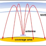
Omnidirectional Magic: Picture a donut lying flat – that’s your radiation pattern. Perfect for general-purpose communication whether you’re chasing DX or chatting with locals.
Budget-Friendly: Built from basic materials that won’t break the bank – just wire, insulators, and coax.Band Versatility: From the mighty 160-meter band down to the compact 70-centimeter band, dipoles work across the entire amateur spectrum.
The Science Behind the Magic
Understanding the Physics
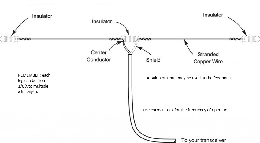
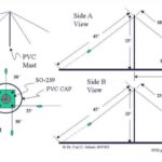
A half-wave dipole consists of two wire elements, each approximately a quarter-wavelength (λ/4) long, fed at the center. The total length follows this fundamental relationship:Basic Formula: L = c/f × 1/2Where:
| BandFrequency (MHz)Popular Use |
|---|
| 160 m1.905Long-distance night communication80 m3.65Regional and DX, especially at night60 m5.3325NVIS and medium-distance40 m7.1Reliable DX, day and night30 m10.125CW and digital modes20 m14.175The DX superhighway17 m18.118Underused gem for DX15 m21.225Excellent for solar maximum12 m24.94Contest and DX10 m28.85Local and skip when open6 m51.0The “magic band”4 m70.25UK-specific allocation2 m145.0Local FM and weak signal70 cm435.0Repeaters and local communication |
Step-by-Step Construction Guide
Step 1: Design Your DipoleChoose your target band and calculate the length:
| BandFrequency (MHz)Quarter-Wave (λ/4)Half-Wave (λ/2)Full-Wave (λ) |
|---|
| 160 m1.90539.37 m78.74 m157.48 m80 m3.6520.55 m41.10 m82.19 m60 m5.332514.06 m28.12 m56.24 m40 m7.110.56 m21.13 m42.25 m30 m10.1257.41 m14.81 m29.63 m20 m14.1755.29 m10.58 m21.16 m17 m18.1184.14 m8.28 m16.56 m15 m21.2253.53 m7.07 m14.13 m12 m24.943.01 m6.01 m12.03 m10 m28.852.60 m5.20 m10.40 m6 m51.01.47 m2.94 m5.88 m4 m70.25106.76 cm213.52 cm427.05 cm2 m145.051.72 cm103.45 cm206.90 cm70 cm435.017.24 cm34.48 cm68.97 cm |
Pro Tips for Success
Environment Considerations: Use THHN insulated wire for permanent outdoor installations. It resists UV degradation and moisture better than bare copper.
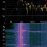
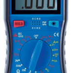
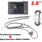
Precision Tuning: A Vector Network Analyzer (VNA) is the ultimate tuning tool, showing not just SWR but also the reactive components. If you have access to one, use it!
Mechanical Integrity: Secure your antenna against wind loading. A broken dipole in a storm is no fun to repair!
Lightning Protection: Keep antennas clear of power lines, use proper grounding techniques, and disconnect during storms. Safety always comes first – we’ve all heard stories of hams who learned this lesson the hard way.Troubleshooting Common Issues
High SWR Across the Band: Check connections, look for water in coax, verify balun installation
Directional Pattern Problems: Ensure the antenna is properly oriented and clear of nearby conductors
Intermittent Operation: Look for corroded connections, especially at the center insulator. Your Next Steps. Building a dipole antenna is one of amateur radio’s most rewarding projects. Start with a single-band dipole for your favorite band – 20 meters is excellent for beginners as it offers worldwide communication with manageable size.Once you’ve mastered the basics, experiment with:Different installation configurations
Multi-band designs: Carolina Windoms and off-center-fed dipoles Use Modeling software to predict performance
“Remember, every expert was once a beginner” who built their first dipole with slightly shaky hands and high hopes. The beauty of amateur radio is in the experimentation and learning.Conclusion The humble dipole has launched countless amateur radio careers and continues to provide reliable service in stations worldwide. With the dimensions and techniques outlined in this guide, plus your SWR meter or VNA for fine-tuning, you’re well-equipped to build efficient antennas for any UK amateur band.Start simple, build carefully, and don’t be afraid to experiment. Each antenna you build teaches you something new about the fascinating world of electromagnetic radiation and propagation.Happy building, and 73!Tell us how can we improve this post?

Hi I am Marcus, MM0ZIF, a licenced Radio Amateur, Doctor of Musicology, amateur weather enthusiast. I over the years have been a Amateur Radio Tutor, Examiner, and a Regional Manager for the Radio Society of Great Britain.
This site is dedicated more towards Amateur Radio and Weather, with an angle on Technology too. I also maintain https://havenswell.com/ which is my other blog which is more aimed at cooking, hobbies and life in general as well as businness and networking.
- MM0ZIF

- MM0ZIF

- MM0ZIF
- MM0ZIF

- MM0ZIF

- MM0ZIF
- MM0ZIF
- MM0ZIF
- MM0ZIF
- MM0ZIF
- MM0ZIF

- MM0ZIF

- MM0ZIF

- MM0ZIF
- MM0ZIF
- MM0ZIF
- MM0ZIF

- MM0ZIF

- MM0ZIF

- MM0ZIF

- MM0ZIF

- MM0ZIF
- MM0ZIF

- MM0ZIF

- MM0ZIF

- MM0ZIF

- MM0ZIF
- MM0ZIF

- MM0ZIF

- MM0ZIF
- MM0ZIF
- MM0ZIF

- MM0ZIF

- MM0ZIF
- MM0ZIF
- MM0ZIF
- MM0ZIF

- MM0ZIF
- MM0ZIF
- MM0ZIF

- MM0ZIF
- MM0ZIF

- MM0ZIF

- MM0ZIF
- MM0ZIF
- MM0ZIF
- MM0ZIF

- MM0ZIF
- MM0ZIF

- MM0ZIF
- MM0ZIF
- MM0ZIF
- MM0ZIF
- MM0ZIF
- MM0ZIF
- MM0ZIF
- MM0ZIF

- MM0ZIF

- MM0ZIF
- MM0ZIF

- MM0ZIF
- MM0ZIF
- MM0ZIF

- MM0ZIF
- MM0ZIF

- MM0ZIF

- MM0ZIF

- MM0ZIF

- MM0ZIF

- MM0ZIF

- MM0ZIF

- MM0ZIF

- MM0ZIF

- MM0ZIF

- MM0ZIF

- MM0ZIF

- MM0ZIF

- MM0ZIF

- MM0ZIF
- MM0ZIF
- MM0ZIF

- MM0ZIF

- MM0ZIF

- MM0ZIF

- MM0ZIF

- MM0ZIF
- MM0ZIF
- MM0ZIF
- MM0ZIF
- MM0ZIF
- MM0ZIF
- MM0ZIF
- MM0ZIF
- MM0ZIF
- MM0ZIF
- MM0ZIF
- MM0ZIF

- MM0ZIF

- MM0ZIF

- MM0ZIF

- MM0ZIF

- MM0ZIF

- MM0ZIF

- MM0ZIF

- MM0ZIF
- MM0ZIF

- MM0ZIF

- MM0ZIF

- MM0ZIF

- MM0ZIF

- MM0ZIF
- MM0ZIF

- MM0ZIF

- MM0ZIF

- MM0ZIF

- MM0ZIF
- MM0ZIF

- MM0ZIF

- MM0ZIF

- MM0ZIF
- MM0ZIF

- MM0ZIF

- MM0ZIF

- MM0ZIF
- MM0ZIF
- MM0ZIF

- MM0ZIF

- MM0ZIF

- MM0ZIF
- MM0ZIF
- MM0ZIF

- MM0ZIF

- MM0ZIF

- MM0ZIF

- MM0ZIF

- MM0ZIF

- MM0ZIF

- MM0ZIF
- MM0ZIF

- MM0ZIF

- MM0ZIF

- MM0ZIF

- MM0ZIF

- MM0ZIF
- MM0ZIF
- MM0ZIF

- MM0ZIF

- MM0ZIF
- MM0ZIF
- MM0ZIF
- MM0ZIF
- MM0ZIF
- MM0ZIF

- MM0ZIF
- MM0ZIF
- MM0ZIF

- MM0ZIF
- MM0ZIF

- MM0ZIF

- MM0ZIF
- MM0ZIF
- MM0ZIF
- MM0ZIF

- MM0ZIF
- MM0ZIF
- MM0ZIF

- MM0ZIF

- MM0ZIF
- MM0ZIF

- MM0ZIF
- MM0ZIF

- MM0ZIF
- MM0ZIF
- MM0ZIF
- MM0ZIF

- MM0ZIF
- MM0ZIF

- MM0ZIF
- MM0ZIF
