
Please note (Featured Image is borrowed from another site, I do not hold the copyright nor know who does!)
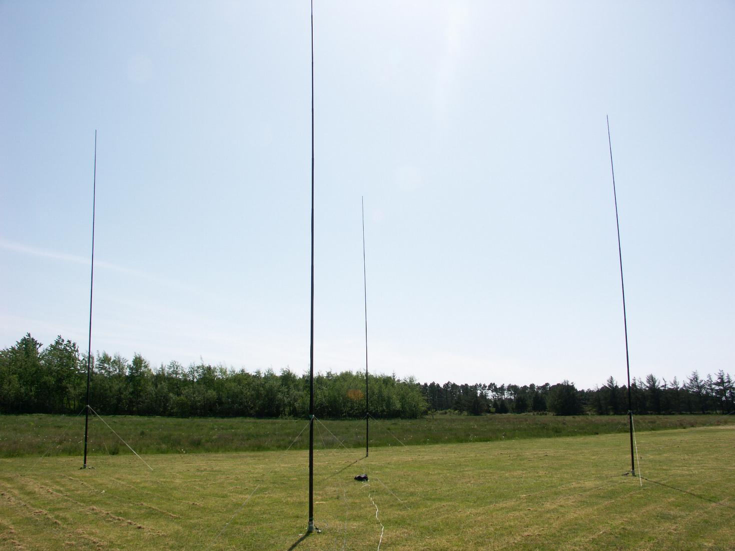
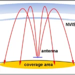
A 4-square array in amateur radio is a type of antenna system that uses four vertical antenna elements arranged in a square. This configuration allows for a directional radiation pattern, meaning the antenna can focus its signal in a specific direction, which is very beneficial for long-distance communication (DXing) and contesting.
Here’s a breakdown of how they work:
- Four Vertical Elements: The system typically uses four vertical antennas, often ground planes or vertical dipoles, placed at each corner of a square.12 The sides of this square are usually about a quarter-wavelength long for the operating frequency.
- Phasing and Amplitude Distribution: The key to the 4-square array’s directivity lies in how the power is fed to each of these four elements. A central component called a “coupler” or “phasing unit” distributes the input power to the radiators with precise amplitude and phase relationships. By changing these phase and amplitude distributions, the direction of the antenna’s beam can be electronically switched without physically rotating the antennas.
- Directional Switching: For a typical 4-square array, the input power is split into four equal parts. Two radiators might have a 0-degree phase difference, while the other two have +90 and -90 degrees relative to the first pair. This precise phasing allows the array to “steer” its signal in one of four directions, usually across the diagonals of the square. This is a significant advantage, especially for lower frequency bands (like 160m, 80m, and 40m) where physically rotating large directional antennas is impractical and expensive.
- Gain and Front-to-Back Ratio: A well-designed 4-square array offers gain over a single vertical antenna, meaning it concentrates more energy in the desired direction. It also provides a good front-to-back ratio, which helps in reducing interference from unwanted signals coming from the opposite direction.
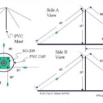
- Components: Beyond the four vertical elements, a 4-square system includes a coupler (or phasing lines), and a radial or ground system. The coupler is crucial for distributing power and managing the phase relationships.
- Applications: 4-square arrays are popular among amateur radio operators for their ability to provide directional control and enhanced performance on the lower frequency bands. They are used for both transmitting and receiving.
Key Considerations for a Budget 40m 4-Square Array
- Frequency: 40 meters (7.0–7.3 MHz, centered around 7.15 MHz for calculations).
- Wavelength: The wavelength for 40 meters is approximately λ = 300 / 7.15 = 41.96 meters. A quarter-wavelength (λ/4) is about 10.49 meters (34.4 feet).
- Antenna Elements: Four quarter-wave verticals, each approximately 33–34 feet tall, with ground radials.Spacing: Elements are spaced λ/4 apart (about 34 feet) in a square configuration.
- Phasing Network: A system to feed the antennas with specific phase differences (0°, 90°, 180°, 270°) to steer the radiation pattern.
- Ground System: Radials or a ground screen to improve efficiency.
- Budget Focus: Use affordable materials like wire, PVC, or aluminum tubing, and consider DIY phasing solutions.
Step-by-Step Guide:
1. Antenna Elements Each of the four verticals needs to be a quarter-wavelength long, resonant at 7.15 MHz.
- Option 1: Wire Verticals:
- Use insulated copper wire (e.g., 14 AWG stranded wire, ~£0.10–$0.20/ft). Each vertical needs ~34 feet, so 4 × 34 = 136 feet total. Cost: ~£15–$30 for wire.Suspend wires from non-conductive supports like fiberglass poles, PVC pipes, or trees. Budget option: 2-inch PVC pipe (~£10 for a 10-foot section, need ~4 sections per vertical for 34 feet, total ~$160). Cheaper: Use surplus fishing poles or bamboo if available.
Option 2: Aluminum Tubing:- Aluminum tubing (e.g., 1-inch diameter, ~£1–£2/ft) can be sourced from hardware stores or scrap metal yards. Each vertical needs ~34 feet, so 4 × 34 = 136 feet. Cost: ~£150–£300, but check for surplus or used materials to cut costs.Mount tubing on insulators or wooden stakes at the base.
Construction:
- For wire verticals, cut each to 34 feet (slightly longer, trim to resonance). Attach to a support structure and keep vertical.For tubing, use telescoping sections (e.g., 6–8 foot lengths) joined with hose clamps. Ensure good electrical connections between sections.Calculate exact length using: Length (feet) = 234 / f (MHz) = 234 / 7.15 ≈ 32.73 feet, then adjust for ground effects (typically 5% longer, ~34 feet).
- Use 16 AWG or 14 AWG wire for radials (~$0.05–$0.10/ft). Each vertical needs at least 8–16 radials, 20–40 feet long. For 4 verticals with 8 radials of 30 feet each: 4 × 8 × 30 = 960 feet of wire. Cost: ~$50–$100.Alternatively, use chicken wire or hardware cloth for a ground screen (~£50 for a 50-foot roll).
Construction:
- Lay radials in a star pattern from each vertical’s base, buried 1–2 inches or on the surface. Staple to the ground with landscape staples (~£10 for 100).If using a ground screen, place it under the array and connect to each vertical’s ground point.Connect radials to a copper ground strap or bus bar at each vertical’s base.
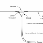
- Use a 90° hybrid coupler (can be built with coax) or a Christman phasing method, which is simpler for amateurs.Christman Phasing: Feed two pairs of verticals with specific coax lengths to achieve 0° and 90° phase shifts. Requires precise coax cutting (RG-8 or RG-58, ~$0.50/ft).Example: For 7.15 MHz, use 1/4-wave coax (accounting for velocity factor, ~0.66 for RG-8): Length = (246 × 0.66) / 7.15 ≈ 22.7 feet for 90° delay.Total coax: ~100–150 feet for feeds and phasing lines. Cost: ~£50–£75.
Switching:
- Use a manual coax switch (~£30 – £50) to select phase configurations for different directions (e.g., NE, SE, SW, NW). Alternatively, build a relay box with surplus relays (~£20–£40) for remote switching.
DIY Phasing Network:
- Construct a simple L-network or transformer-based phasing box using toroids (e.g., T-200-2, ~£5 each, need 2–4) and capacitors (~£10). Total cost: – £30–£50. Follow designs from ARRL Antenna Book or ON4UN’s Low-Band DXing for schematics.
Tell us how can we improve this post?

Hi I am Marcus, MM0ZIF, a licenced Radio Amateur, Doctor of Musicology, amateur weather enthusiast. I over the years have been a Amateur Radio Tutor, Examiner, and a Regional Manager for the Radio Society of Great Britain.
This site is dedicated more towards Amateur Radio and Weather, with an angle on Technology too. I also maintain https://havenswell.com/ which is my other blog which is more aimed at cooking, hobbies and life in general as well as businness and networking.
- MM0ZIF

- MM0ZIF

- MM0ZIF
- MM0ZIF

- MM0ZIF

- MM0ZIF
- MM0ZIF
- MM0ZIF
- MM0ZIF
- MM0ZIF

- MM0ZIF

- MM0ZIF

- MM0ZIF
- MM0ZIF
- MM0ZIF
- MM0ZIF

- MM0ZIF
- MM0ZIF

- MM0ZIF

- MM0ZIF

- MM0ZIF

- MM0ZIF
- MM0ZIF

- MM0ZIF

- MM0ZIF

- MM0ZIF

- MM0ZIF
- MM0ZIF

- MM0ZIF
- MM0ZIF
- MM0ZIF
- MM0ZIF

- MM0ZIF

- MM0ZIF
- MM0ZIF
- MM0ZIF
- MM0ZIF

- MM0ZIF
- MM0ZIF
- MM0ZIF

- MM0ZIF
- MM0ZIF

- MM0ZIF

- MM0ZIF
- MM0ZIF
- MM0ZIF

- MM0ZIF

- MM0ZIF
- MM0ZIF

- MM0ZIF

- MM0ZIF
- MM0ZIF
- MM0ZIF
- MM0ZIF
- MM0ZIF
- MM0ZIF
- MM0ZIF

- MM0ZIF

- MM0ZIF
- MM0ZIF

- MM0ZIF
- MM0ZIF

- MM0ZIF

- MM0ZIF
- MM0ZIF

- MM0ZIF

- MM0ZIF

- MM0ZIF

- MM0ZIF

- MM0ZIF

- MM0ZIF

- MM0ZIF

- MM0ZIF

- MM0ZIF

- MM0ZIF

- MM0ZIF

- MM0ZIF

- MM0ZIF

- MM0ZIF
- MM0ZIF
- MM0ZIF

- MM0ZIF

- MM0ZIF

- MM0ZIF

- MM0ZIF

- MM0ZIF
- MM0ZIF
- MM0ZIF
- MM0ZIF
- MM0ZIF
- MM0ZIF
- MM0ZIF
- MM0ZIF
- MM0ZIF
- MM0ZIF
- MM0ZIF
- MM0ZIF

- MM0ZIF

- MM0ZIF

- MM0ZIF

- MM0ZIF

- MM0ZIF

- MM0ZIF

- MM0ZIF

- MM0ZIF
- MM0ZIF

- MM0ZIF

- MM0ZIF

- MM0ZIF

- MM0ZIF

- MM0ZIF
- MM0ZIF

- MM0ZIF

- MM0ZIF

- MM0ZIF

- MM0ZIF
- MM0ZIF

- MM0ZIF

- MM0ZIF

- MM0ZIF
- MM0ZIF

- MM0ZIF

- MM0ZIF

- MM0ZIF
- MM0ZIF
- MM0ZIF

- MM0ZIF

- MM0ZIF

- MM0ZIF

- MM0ZIF
- MM0ZIF

- MM0ZIF

- MM0ZIF

- MM0ZIF

- MM0ZIF

- MM0ZIF

- MM0ZIF

- MM0ZIF
- MM0ZIF

- MM0ZIF

- MM0ZIF

- MM0ZIF

- MM0ZIF

- MM0ZIF
- MM0ZIF
- MM0ZIF

- MM0ZIF

- MM0ZIF
- MM0ZIF
- MM0ZIF
- MM0ZIF
- MM0ZIF
- MM0ZIF

- MM0ZIF
- MM0ZIF
- MM0ZIF

- MM0ZIF
- MM0ZIF

- MM0ZIF

- MM0ZIF
- MM0ZIF
- MM0ZIF
- MM0ZIF

- MM0ZIF
- MM0ZIF
- MM0ZIF

- MM0ZIF

- MM0ZIF
- MM0ZIF

- MM0ZIF
- MM0ZIF

- MM0ZIF
- MM0ZIF

- MM0ZIF
- MM0ZIF

- MM0ZIF
- MM0ZIF

- MM0ZIF
- MM0ZIF


